

This article describes critical electrical components that support data centre resilience. It then covers how failure of these components can disrupt power availability, system continuity and overall operational capability.
1. Understanding Individual Data Centre Components
To understand how individual components (or equipment) interact with overall data centre infrastructure and systems we need to identify the critical electrical components. These are directly involved in conditioning, protecting and delivering uninterrupted power to the IT servers. Each critical component has a role and responsibility to interact with other equipment. They all need to work together, and it is imperative that this equipment is fully maintainable throughout its design life.
There are multiple critical electrical components in data centres:
- High voltage switchgear (HV)
- Transformers
- Generators
- Low-voltage switchgear (LV)
- Bus couplers
- Uninterruptible power supplies (UPS)
- Static switches
- Power distribution units (PDU’s)
- Power cables
There is also additional, facility-related equipment related electrical equipment:
- Building management system (BMS)
- Fire alarm system
- VESDA System (Very Early Smoke Detection Apparatus)
- Water leak detection systems
- Security systems i.e. CCTV & intruder detection
Below is more detail of the critical electrical components serving data centres.
Data Centre Components and Redundancy

The modern data centre is normally designed with resilience in mind. Typically following the baseline rule for component redundancy, N+1, where N = critical components and the +1 allows for an additional redundant component.
For example, if a server hall requires 8 cooling units to maintain set temperatures, 9 units will be installed following N+1. Greater resilience e.g. 2N or 2(N+1) may be required depending on the type and requirements of the data centre.
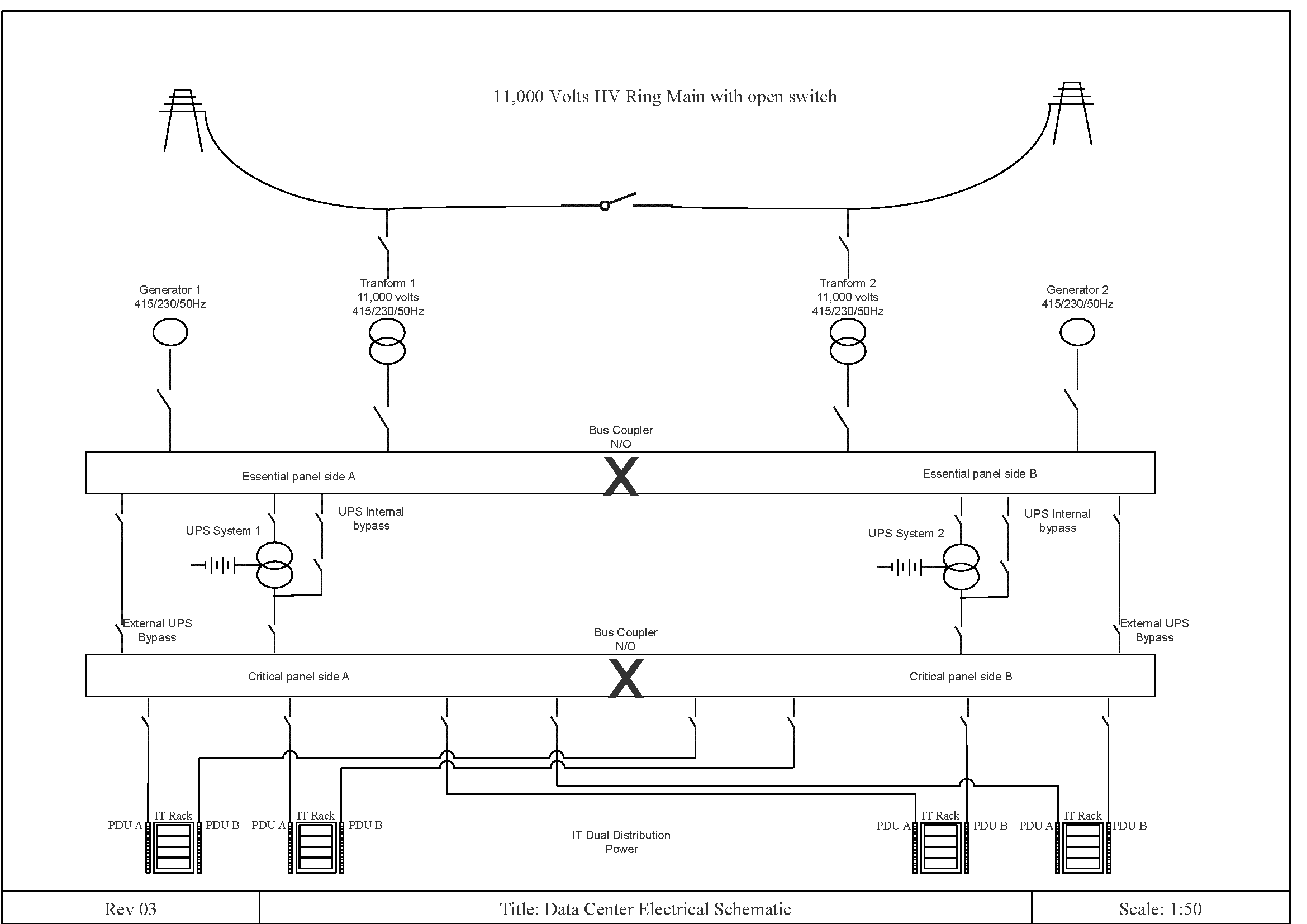
As you can see from the single line drawing below, data centres rely on redundancy as it is critical to always maintain IT power availability. To do this, there must be dual power supplies not only for resilience but for maintainability.
Transformers
Transformers decrease high-voltage electricity from the utility grid down to safer, lower voltage levels for power transmission and distribution. The single line drawing shows two transformers fed from the main HV ring main. The ideal scenario is to negotiate with the Power Utility or Distribution Network Operator (DNO) to have the HV ring switch in the open position providing maximum resilience.

If one side of the ring has a power outage, the other half of the ring is still maintaining HV Power Support to the alternative transformer maintaining LV Power to the B supply.
Generators
Generators are used in case of mains failure. Generators are provided on both incoming supply paths A & B. During the mains failure of either A or B supply the generators will start up automatically and support the load. The interaction normally takes between 15 and 20 seconds for the generator to start up and support the building load. During this mains power interruption of main to generator changeover the UPS systems will support the critical IT load.
Bus Couplers
Bus couplers act as electrical switches that connect or isolate two separate power distribution buses. Their primary job is to keep server racks powered during maintenance or equipment failures by rerouting electrical paths. The single line drawing shows Bus couplers that are energised during a mains power outage on either side of the incoming A or B supply.
Uninterruptible Power Supplies
The single line drawing shows two UPS systems, one on each resilient path A & B. UPS systems are made up of rectifier and inverters with thyristors. AC Power feeds the rectifier. The rectifier converts the power into DC then feed the inverter. The inverter converts the power back to AC. During the conversion state, this is where the batteries are added which are constantly in recharge mode and available for any power anomaly or power interruption, including brownouts and blackouts.
Power Distribution Units
PDU’s are used within the data centre space. These provide multiple power cable connections for distribution to IT racks. From the single line drawing, you can see two power supplies feeding into an IT rack providing resilience. Each power supply is fed from alternative resilient paths A & B.
Power Cables
Cable infrastructure is very important during the installation of the data centre. Even before the cables are installed it is critical to have the cable sized correctly with loading parameters and discrimination studies, including protective devices to prevent cable overheating or short circuits due to design or installation failures.

Summary of Data Centre Critical Components
All the above critical electrical components are necessary to support the IT load without interruption. They must be maintained as per the manufacturer’s instructions and constantly monitored as there are thousands of sub-components that can fail at any time. Although most components are resilient during their design life, from time to time these components can fail, sometimes without notice resulting in a catastrophic system failure.
2. The Impact of Data Centre Component Failures
Data centre component failures matter because even a small fault can have consequences far beyond the failed item itself. In environments where continuous power, cooling and connectivity are essential, the loss of a transformer, generator, UPS, bus coupler, PDU or cable can rapidly affect resilience, service availability, fire safety and the ability to maintain critical IT load.
Transformers
Transformers are a reliable equipment with very little components. There are two types of transformers used in data centres.
- Dry transformers with air cooled fans
- Wet transformers with oil cooled convection
Both transformers have a primary and secondary copper coil that takes the high voltage to low voltage. Depending on the load, the size of the transformer will vary.
Component failures are very rare, but in some cases and poor maintenance the transformer can overheat and destroy itself causing a catastrophic failure. Once the transformer is off-line, there is no power to the data centre supply. This means the UPS must support the IT critical load. The UPS will have a limited battery autonomy which means other electrical equipment must be operated to prevent IT critical load failure. This is done by the main LV panel whereby the Programmable Logic Controller (PLC) will detect mains failure from the transformer and carry out a sequence of controls to initialise the bus coupler. Once the bus coupler has closed, the power is restored, fed from the alternative supply.
Generators
Failure on a generator is very rare but can happen. Failure of the electronic governor is the most common. The electronic governor is a mechanical/electrical device that injects diesel fuel into the engine to maintain speed and load requirements. This piece of equipment is a single point of failure (SPOF) and can cause a fault even before the generator has started.
The electronic governor failure will cause the generator to stop immediately as its built-in software will detect anomalies and to prevent the engine from being damaged will shut it down immediately.

Once the generator is offline, there is no power to the data centre supply. This means the UPS must support the IT critical load. The UPS will have a limited battery autonomy which means other electrical equipment must be operated to prevent IT critical load failure. As above, this is done by the main LV panel whereby the PLC will detect mains failure from the generator and carry out a sequence of control to initialise the bus coupler. Once the bus coupler has closed, the power is restored, fed from the alternative supply.
Bus Couplers
Bus couplers are critical components situated within the main LV panel, controlled via the Programmable Logic Controller (PLC). Normally in the open position but awaiting instructions from the PLC to close when there is a loss of supply on either the A or B supply. As these bus couplers only operate when required there are several electrical and mechanical sub-components requiring maintenance on a regular basis, including:
- Contactor
- Micro switches
- Shunt trips
- Solenoids
- Springs
If any of the above listed sub-components fail, the bus coupler will fail to operate. There are no alarms attached to this component, so it is imperative it is maintained and operated on a regular basis. If the bus coupler fails to operate, there is a high risk of losing power to one side of the LV board during upstream, power interruptions. At this point manual intervention is needed to figure out what is wrong and manually operate this device using trained personnel.

Uninterrupted Power Supply (UPS)
There are several types of UPS systems
- Rotary
- Static
- Modular
The UPS needs to convert alternating current (AC) to direct current (DC) and then back to AC. The reason for this is to have a common DC Bus where the batteries are connected and this conversion also cleans up the power supply and frequency. The UPS has multiple sub-components:
- AC capacitors
- Batteries
- Cooling fans
- DC capacitors
- Diodes
- Heat sinks
- Inverters
- PC control boards
- Rectifiers
- Static switches
- Thyristors
Some of the above typically have a design life of only five years, including:
- AC capacitors
- Cooling fans
- DC capacitors
Batteries tend to be designed for 7 or 10 years; however, they are normally changed out at five years to prevent failure. If any of the above listed components fail, the UPS will shut down. Once the UPS is offline, there is no power to the IT load. This means the alternative UPS supply will support the IT critical load seamlessly. As there is no upstream power outage the alternative UPS can support the load indefinitely until the failed UPS can be repaired and brought back into service.
Power Distribution Units (PDU)
The power distribution unit is a very large consumer unit with hundreds of cables terminated in one place with protective circuit tripping devices. PDUs themselves do not normally suffer with failures however the tripping devices are there to protect the downstream circuit/equipment and cables.
As PDUs provide multiple cable connections you would not normally see a failure of this device unless the installation and termination of cables are incorrect and consequently overheat and catch fire. However, regular maintenance of the PDU including electrical testing and thermal imaging can eliminate this potential threat.

Power Cables
Cables are a major component within a data centre. They provide power from the PDU to the IT rack which feeds critical IT equipment. As a component, cables do fail and can suffer the following:
- Bad connections
- Inappropriate installation
- Installed in harsh environment conditions
- Overheating
- Overloading
All the above can cause loss of power to the critical components and an increase in risk of fire. It is imperative that these components are maintained, inspected and comply with internationally recognised standards.
In summary, data centres depend on a complex network of electrical components to maintain uninterrupted power, cooling and operational continuity. While redundancy is built into modern facilities, the failure of individual components can still create significant disruption, fire risk or loss of critical IT load if not properly managed. Regular maintenance, monitoring and inspection are therefore essential to reduce the likelihood of failure and support long-term resilience.
